Art
Computing
Contact info
CV
Electronics
Geek culture
Home brewing
Math
Music
Physics
Rants
Ψ/Φ
Style
Teaching
Theatre
WHAT'S UP
As I have grown very unsatisfied with my Radiotehnika U-7111 integrated amplifier, I have gained many ideas concerning what I want from an amplifier. In fact, what I don't want; I believe many problems with sound quality and general usage come from the controls and features I never use. I only want volume control, and even that is included in my computer's sound card and my CD player. Therefore, what I want is a power amplifier.
Unfortunately, non-integrated (differentiated? :-) amplifiers belong to the mid/high end of audio equipment spectrum, which I won't be able to afford quite yet. On the other hand, a power amplifier can be made quite simple so I could build one, possibly from a construction kit.
It was a something of an enlightenment to me when I heard of GainClones like this one earlier this year (2003). Here was a very simple circuit for a very high quality power amp. The simplicity goes well with my minimalist ideals and means less noise in general because each component generates some noise by itself. More interestingly, it allows one to invest in quality components, and leaves more choice for the enclosure as the circuits won't take up much space.
Like many others I was initially wary of using operational amplifiers in a HiFi setup. I am used to hacking with those ICs when doing simple signal processing or measurement, which is a good starting point though. It seems that this new generation of power opamps is simply taking the 'ideal opamp' concept further, as they can deliver enough current to drive decent speakers. LM3875 is the IC of choice here, the one I will be using too.
Apparently the LM38xx opamps do not need excessive filtration with the power supply, and the recommendation seems to be to keep the supply as simple as possible, with high quality diodes — just like the rest of the amp. I'm getting high on this all-encompassing minimalism :-P.
I have salvaged a suitable transformer and diodes from a late Technics amplifier. In fact I used the same trafo' in the Radiotehnika as its original one was a little noisy. The Technics amp had no fancy filtering either so I think its diodes are good enough, and of course I can upgrade them later as I see fit.
Because of the transient nature of music waveforms, you still need largish elcas to provide the punch. The GainClones generally have 2x1000μF attached next to each opamp, which seems good from my technical point of view too. I'll add two caps for the power supply section as well, just to be sure.
The 1-mF caps may seem a little small for something that can provide 100W per channel, but for these ICs it is enough. Bigger caps 'just for sure' are not necessarily better, as I've learned that they operate a little slower. In fact some high end equipment have several smaller elcas in parallel to counter this effect.
For the sake of a possible E2 contribution, the schematics are in ASCII.
                             V+
     Amplifier,              |
     one channel             |    1 mF
                             |  +||-
                             +---||----> GND
                             |   ||
                             |
                      +----- | ---#####---+
Input                 |      |1    220k   |
       ||      10k    |   7|\|            |
  (+)--||-----#####---+----|-\ 3          |
      +||-                 |  >-----------+----------------(-)
      4.7 uF        GND <--|+/ LM3875                          Speaker
                          8|/|                      GND <--(+)
  (-)---> GND                |4
                             |    1 mF
                             |  -||+
                             +---||----> GND
                             |   ||
                             |
                             |
                             V-
Note in particular: this is an inverting amplifier, so the speaker is connected in inverted fashion to preserve the phase. According to some GainClone gurus this is less noisy than the non-inverting version, though the differences are probably minuscule. Otherwise this is a very basic opamp circuit with a voltage gain of 22.
The capacitor at the input is meant to kill any unwanted DC component. You can check that it doesn't really affect sound frequencies, except perhaps something below 20Hz which my speakers won't play anyway :-). It turned out quite useful as my CD player's headphone output was b0rken and the left channel was all DC :-/.
The power supply is simple, consisting of a transformer, a bridge of diodes, and two 1 mF elcas for some extra oomph. I get about +/- 35V and the elcas are rated at 63V (because the 35V is RMS).
                                         GND
   Power supply                           ^
                                        - |
                                        ===== 1 mF
                                        + |
                                          |
                         +--|>|-----------+--------> V+
                         |                |
                         |                |
()---------o o-----------+        +--|>|--+
           o o           |        |
Mains      o o--> GND    +--|<|-- | ------+--------> V-
           o o                    |       |
()---------o o--------------------+--|<|--+
                                          |
                                        - |
                                        ===== 1 mF
                                        + |
                                          |
                                          V
                                         GND
I chose Vero boards separate for each channel and the power supply. Not very professional, but great for tweaking later on. Since GainClones are so simple, many people build them directly without any PCB, but I think these are easier to mount into enclosures, and neater in general.
Thick cables are a must, there's no point in having good speaker cables if the inside of the amp consists of hairlike threads. On the other hand the Vero board had quite small-bore holes. I ended up drilling them with a 1-mm bit for cables and bigger components; the cabling was medium quality speaker cable. For line inputs I used microphone cable; I wanted them well shielded as the inputs are already attenuated outside the amp.
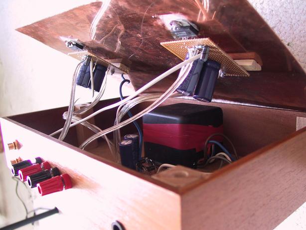
The 1 mF elcas should be as close as possible to the IC. I didn't get them quite optimally because of their size, and I'm also a bit concerned about the resistance of the Vero board compared to direct mounting, but it sounds so good I can't complain. See the next section :-)
There are also some general considerations like avoiding ground loops. Again I must state that this is not a beginners' manual so I won't go into these basic details, but of course you can ask me about anything via email or otherwise.
After some experimentation I've moved the trafo as far from the ICs as possible, and earthed the case plate. Both operations reduced mains noise quite substantially and there's not much left :-). Of course the ICs have to be well insulated from the sink, as their tab sits at V-.
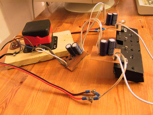
On 24/06/2003 I built the first iteration, just the electronics. First I completed just one channel plus the power supply, checked for any DC offsets (might ruin the speakers) and then checked with an utterly crap speaker if it works at all. It sounded surprisingly nice for such a plastic box, so I completed the other channel and hooked up my main speakers, the JPW Mini Monitors that have won several tests.
Here it is: two channels mounted on the black heatsink, plus the transformer and the rectifier section. Note how the ICs are mounted below the board; it will be useful in the later version where the heatsink/case extends below the board and it must be insulated well.
I'm probably a little biased as I haven't listened to music properly for over two weeks, and the fresh new setup sounded thoroughly majestic. But for a little objectivity, the general feeling is very crisp, tight and exact, even unforgiving. Some old tracker modules sound worse than before, because all those little glitches are more audible. However, for most real music and particularly instrumental kind, the effect is that I can't contain myself, it is just sheer beauty flowing from the speakers. Everything is so detailed and precise, it is easy to pick up those little things that you never hear when listening something for the first time. The brutal frankness is occasionally a little irritating as I'm used to more blurred sounds (and unconsciously deconvolving to sharpen them :-), but I think this is for the good. If the music is supposed to be softer, the producers should take care of it.
This is not surprising after reading other people's GainClone experiences. However, the crisp and tight feeling extended to the very bass where it was most easily heard. For instance, bass keys on the piano (in Lenni-Kalle Taipale's recordings) have never sounded like this on my previous amps. It's hard to describe. I'm really tripping on these listening experiences. :-D I mean really, it's like getting new glasses and seeing things more clearly after a long blurry time.
(09/07/2003) Because the flat frequency response is not exceptional in audio devices, I'm starting to think GainHog's clarity is due to other factors, namely phase response. It is sometimes argued that humans cannot hear the absolute phase of a signal, but I believe the phase congruency does have an effect on attack and decay characteristics. This is where the clarity really seems to come from; long, sustained sounds are not changed that much compared to other amps.
For example, if you take the Fourier components of a square wave and shuffle the phases, the resulting waveform will have gentler curves, despite having the same frequency distribution. A sharp attack needs to have all of the components in a rising phase (i.e. maximum phase congruency). I think one reason why opamps are so good at this is because their frequency range goes up to hundreds of kHz. It also makes one question the 20kHz limit of human hearing. Fortunately I can still use my GainHog when I get new, higher-bandwidth sound sources :-).
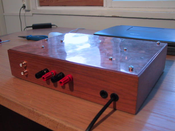
First of all, I wanted to use a metallic case as the heatsink, so that I can completely close the box. I don't want any dusty air wandering inside, and I want a simple, solid look. It's amazing how few cases of this style have been made. Especially with computers, it seems utterly silly to enclose and isolate the heat sources inside the case, and then add massive cooling fans and sinks, when you could make it a lot simpler by exposing the heatsink to the surrounding air.
Salvaged from an old record player, I have a veneer case measuring about 23x31x7 cm3, and it's missing the top plate. In its place I'm using 1.5-mm copper plate that's left over from my Theremin project and other hacks. It looks nice with the semi-dark wooden case, and should be more than sufficient as the heat sink. The main drawback is the screws/bolts that are needed to fasten the ICs and the case itself, and I haven't found anything really cool. Though upgrading the screws is always possible :-).
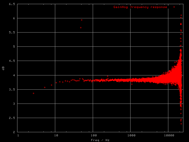
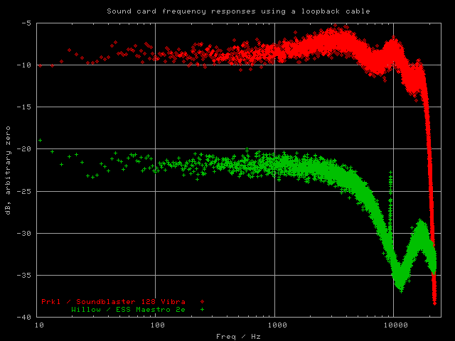
This measurement is not very professional and not to be taken too seriously. It was done on 06/07/2003 with my computer Prkl which has a Sound Blaster 128 card, in roughly the following stages:
The response is really as straight as can be measured this way. The sound card seems to have slight problems with the high frequencies, which were seen in the cable-only response, and might explain the uncertainties here. Of course everything diverges at 22.05 kHz which is the hardware limit.
The infrasound region, while not relevant for any speakers I've used, is well in accordance with the DC offset protector capacitor that's mentioned in the schematics. In summary, it's definitely not bad that everything stays within a fraction of a decibel :-), considering you usually need a dB or three to hear any difference. On the other hand, every deviation from flat corresponds to a convolution in time...
The measurement was made without any speaker load, and another test with the speakers on didn't show any noticeable difference. After all, this is a voltage amplifier, and I could not measure the current response. This is an interesting point because there are other kinds of amplifier around even within the audiophile scene. For instance NPN and PNP transistors are the most linear when used as current amplifiers. This probably has a slight effect on the sound quality too.
This kind of amplifier is usually known as GainClone or a variant thereof, after the original commercial amp named GainCard. My choice of GainHog should not be that surprising, and it also reflects my desire to have a simple power amplifier — just the gain, ma'm.
There are lots more GCs around, here are the main sources I used: